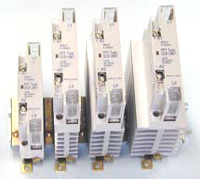
For Sale - SRP - 3172 - Power Controller


Reference Numbers
SRP - 3172Product
Power ControllerManufacturer
Mifa Systems, IndiaSynchronous Firing (Zero Cross Over):
This is also commonly known as zero cross over firing or burst firing method. In this technique, we trigger the scr at the moment sine wave crosses zero and the anode is driven positive, the power control is achieved by having the scrs on for some cycles and off for other cycles. The ratio of no. of cycles On to no. of cycles Off is varied to proportional the power delivered to the load.
Advantages of Synchronous Firing:
- Conventional voltmeters and ammeters can be used for instrumentation at 50 percent to 100 percent voltage range
- Infinitely variable output
- Elimination of RFI
- More uniform power distribution
- No flickers on the lighting load
- Achieves near unity power factor
Phase Angle Firing:
In this method, thyristor is triggered in every cycle. Basically we are delaying the scr gating until some time after the voltage crosses the zero, by varying this delay (measured in electrical degrees) in turn we are controlling the conduction i.e. the On time, and as such the power output to the load is controlled.
There are certain applications which require continuous proportional power. Even certain heating elements requires only phase angle type power controller, namely silicon carbide, super kenthal, infrared heaters and transformer coupled heaters.
In certain closed loop applications the phase angle power controller gives more flexibility and it accepts various feed back signals. With phase angle power controller, the application engineer gets the options of current limiting feature, voltage limiting feature, constant current mode, power feed back, constant KW output and even true rms power controlling.
The power control should be selected considering the line voltage variation and change in the resistance of element with respect to temperature. Another important thing is that, supply cable must be rated at rms current drawn by the element (i.e. current = power / thyristor output voltage and not power / supply voltage).
Following is the few basic configurations, which we generally use for our various industrial applications as shown in figure.
- 1 or 2 phase, 2 Wire connections
- 3 phase, 3 Wire Star connections
- 3 phase, 4 Wire Star connections
- 3 phase, 3 Wire Closed Delta connections
- 3 phase, 6 Wire Open Delta connections
(For picture, please see next page)
For More Details Contact:
Mifa Systems
Mr. Abhay Upadhye
Tel.: 079 - 26870825 / 26870885 / 26871367
E-mail: sales@mifasystems.com, info@mifasystems.com

