For Sale - PTP - 3336 - Web Aligner Guide


Reference Numbers
PTP - 3336Product
Web Aligner GuideManufacturer
C. Trivedi & Company, India应用程序:
1. CT-Tracking Roller Assembles:
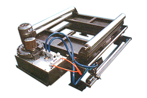
CT-Tracking Roller Assembly (TRA) consists of two rectangular steel tubing frames. One is stationary, the other is movable; it is supported in a nylaguide sliding block and arcuate bar system, and has AB idler roller at either end. The web can be fed over the TRA in a 'U' shaped path, reversing its direction of travel, or thought the TRA in a 'z' configuration .maintaining the same direction of travel. It is insensitive to attitude and can even be mounted upside down. Solidly supported on all four corners by nylaguide bearings, it is not subject to deflections caused by cantilever stresses. Radial bearings are sealed, and linear bearings are self-lubricating. The unit therefore requires no maintenance.
2. The principle:
The TRA is designed so that it swings in an arc laterally, pivoting about an imaginary pivot point located exactly in the plane of the entering web path. The servo cylinder swings the other end of the frame, moving the outgoing web laterally back into the desired web path. Because the TRA correction range is increased by lengthening the span. Therefore the correction angel can be kept small to reduce induced stresses to the level desired. Because stresses can be kept minimal, the TRA can be used to guide within the tension loop on your process. It can be installed successfully on lines handling fragile material such as parchment paper, thin metal foil, or saturated paper even when other guiding methods have failed. It can also be used to make extremely large corrections in the web path, even displacing the shifting unwind, because of its very low inserted stress level.
3. Center Guide System:
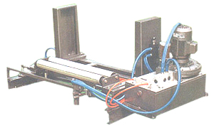
CT movable sensor guide systems are used primarily on processes to center the print regardless of web width variations during the process. The system will sense web width variations up to four inch with moving the sensor or affecting results, an in most case will eliminate misprint process. Center guide can be used where great width variations. Its uses two air flow sensor each mounted on a nylaguide block and bar support connected to opposite sides of a common cable and two pulley arrangement. A single servo cylinder drive the air flow sensor in opposite direction the airflow censor in opposite direction the airflow sensor are there for always equal distant from the material centre line.
One air flow sensor signals a power unit first which activates the servo cylinder the other air flow sensor give signals to second power unit which activities the pivot assembly. Through very reliable and able to a adjustor width changes automatically.
4. Description:
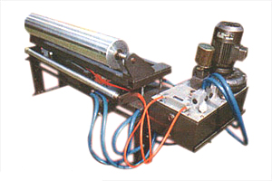
Standard adapter bases consist of a stationary floor-mounted frame or plate, for unit, standard nylaguide bearing and support system, and a moving frame or plate. A heavy duty servo cylinder is nested between the frames and the nylaguide bearings. The servo cylinder moves the upper adapter base plate back and forth in response to hydraulic signals from the power unit.
(For picture, please see next page)
For More Details Contact:
C. Trivedi & Co.
Mr. Bharat Trivedi
Tel.: +91-79-4008 3551 / 4008 3552 / 4008 3553
E-mail: ctrivedi@ctrivedi.com, info@ctrivedico.com

